Description
Universal garage door opener safety sensors
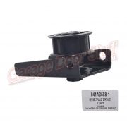
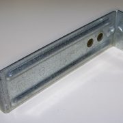
Mounting brackets and instructions included
See instructions below
Garage Door Opener Photo Cells
Garage Door Opener Safety Sensors
Replacement Beam Sensors
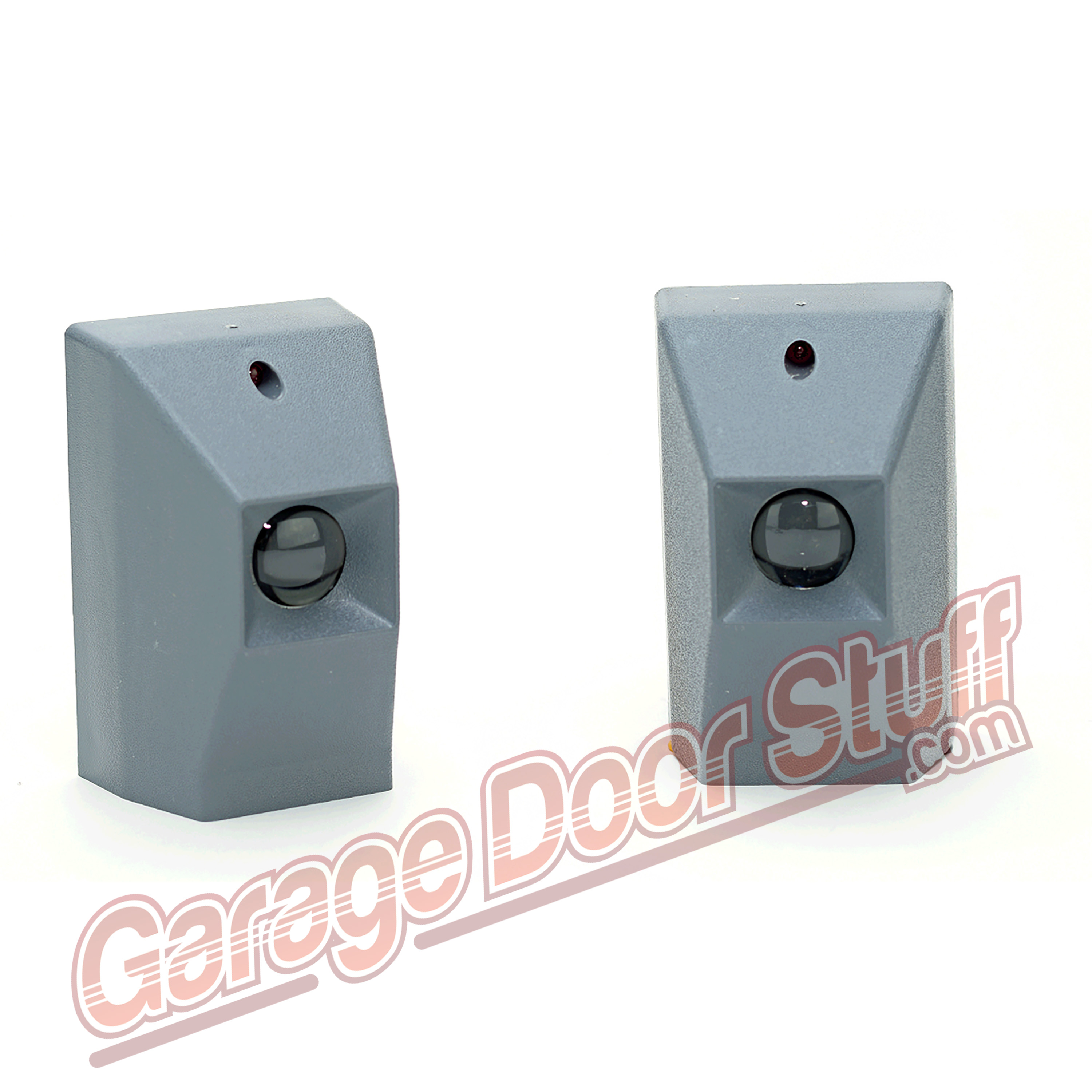
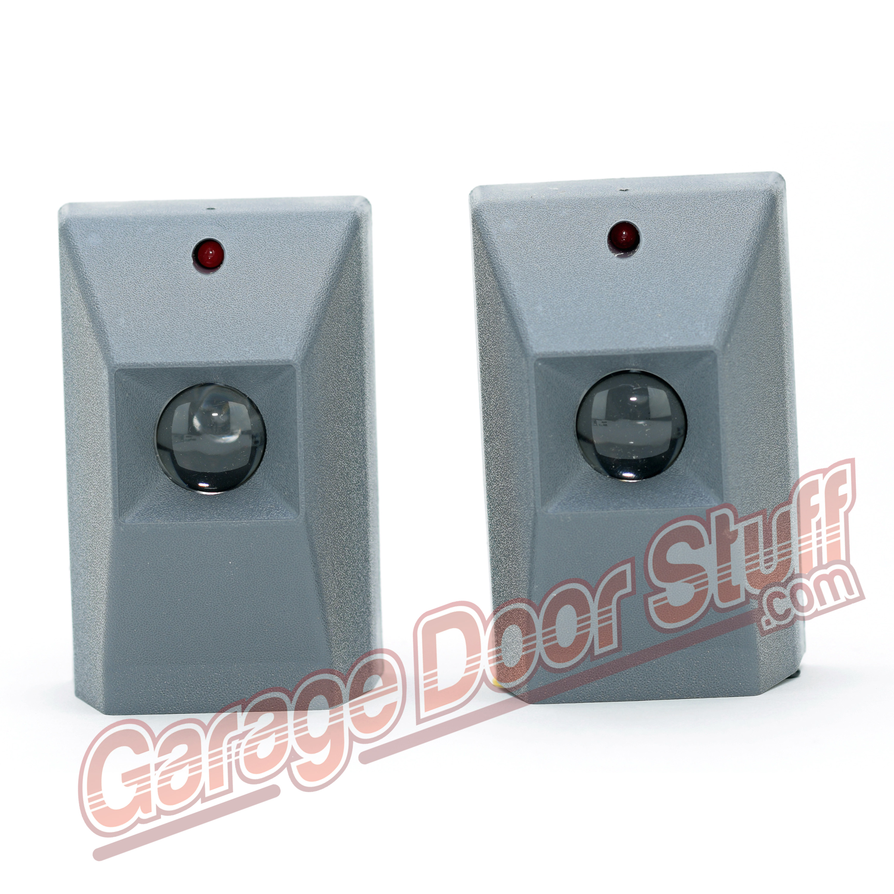
Model CR2149 Universal Beam Sensor
The universal beam sensor works with all major brands of garage door openers – Chamberlain®, Liftmaster®, Craftsman™, Overhead® (1995+), Genie™, Challenger®, Stanley®, Linear®, Moore-O-Matic® and Raynor® models ( built by Chamberlain® ). The beams have a self programming feature which allow the installer to simply hook up the beams to the existing wiring, mount the units to the wall and the job is complete.
This unique product provides the following features:
- Superior filtering from sunlight
- Reduces your inventory of replacement beams
- Competitively priced
- Quick retrofit installation
- Non-polarized ( so there is no way to hook them up backwards )
Now you can go out to a job site with one of these universal beams on the truck and feel comfortable that you can solve the beam sensor problems without having to return.
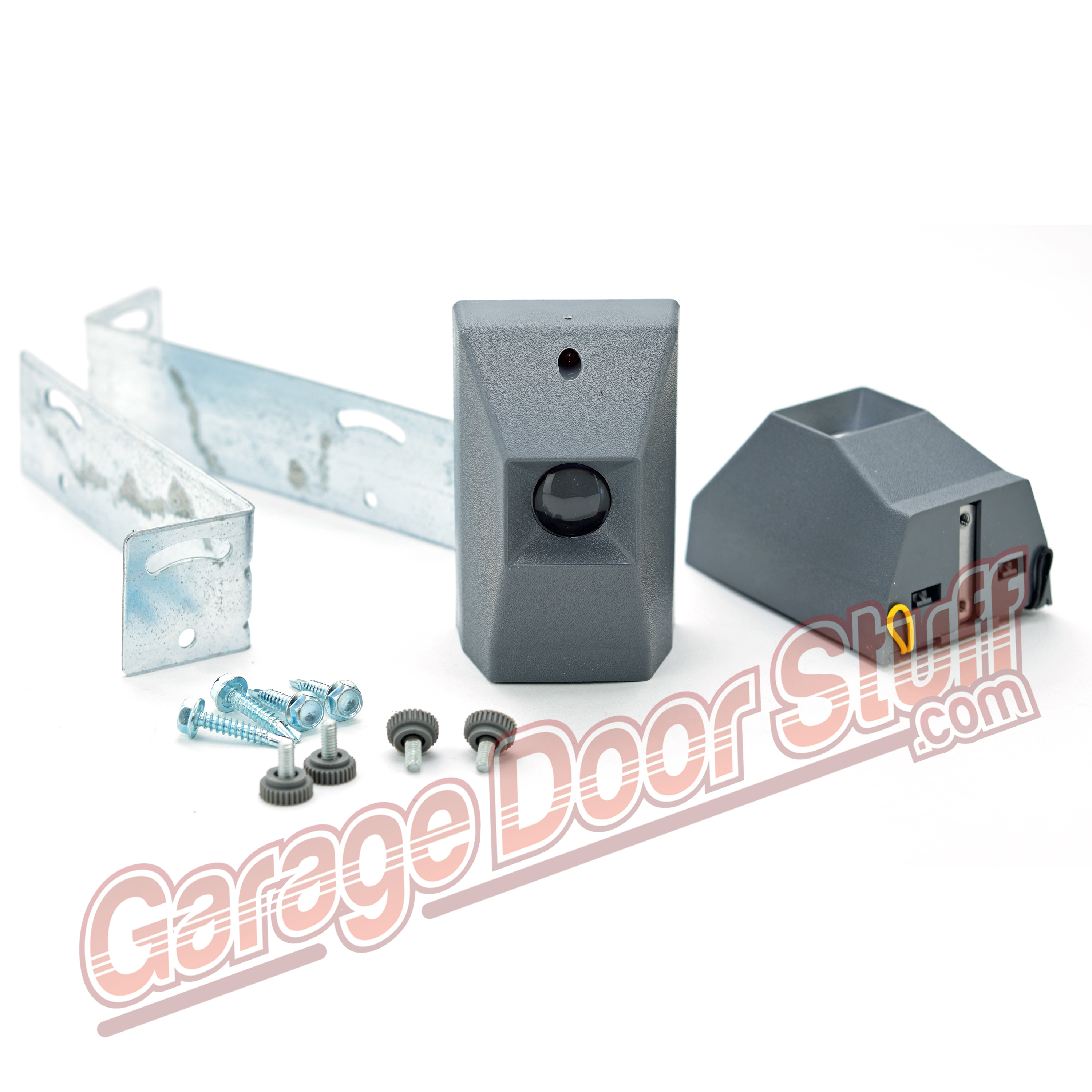
The Universal Replacement Beam Sensor Kit includes:
One Sender and One Receiver Module
Two Mounting Brackets
Four Wood Screws
Instruction Sheet
** WARNING – BEAMS MUST BE INSTALLED NO MORE THAN 2” – 4” ABOVE THE FLOOR **INSTALLATION INSTRUCTIONS UNIVERSAL BEAM SENSOR
The Model CR-2147 ( Sender ) and CR-2148 ( Receiver ) Universal Beam Kit is compatible with the following brands of openers:
Chamberlain, Lift-Master, Craftsman, Genie, Overhead ( 1995+ ), Challenger, Stanley, Linear, Moore-O-Matic and Raynor models ( built by Chamberlain )
TO REPLACE CHAMBERLAIN, LIFT-MASTER, CRAFTSMAN, GENIE, OVERHEAD ( 1995+ ), LINEAR OR RAYNOR BEAMS:
1 ) Leave the existing wiring in place ( unless it’s defective ) and remove the beams to be replaced along with their brackets. If the existing wiring is defective, replace with comparable wiring ( not provided ).
2 ) Install the brackets provided at the !same height of the beams you have just removed.
3 ) Mount the new beam sender and receiver on opposite brackets and connect existing wiring, split it between the two screw terminals on the modules. The new units are NON-POLARIZED, so you can hook up the wires either way.
4) Align the two beams so that the red led is on solid on both units. The red led on the sender will light once power is supplied, but the led on the receiver will light only when the units are properly aligned. The opener will now operate as normal.
TO REPLACE MOORE-O-MATIC ( BLACK BEAMS ) OR CHALLENGER BEAMS:
1 ) Clip the BLACK jumper wire sticking out of the back of the new receiver unit.
2 ) Leave the existing wiring in place ( unless it’s defective ) and remove the beams to be replaced along with their brackets. If the existing wiring is defective, replace with comparable wiring ( not provided ).
3 ) Install the brackets provided at the !same height of the beams you have just removed.
4 ) Mount the new beam sender and receiver on opposite brackets and connect existing wiring, split it between the two screw terminals on the modules. The new units are NON-POLARIZED, so you can hook up the wires either way.
5) Align the two beams so that the red led is on solid on both units. The red led on the sender will light once power is supplied, but the led on the receiver will light only when the units are properly aligned. The opener will now operate as normal.
TO REPLACE MOORE-O-MATIC ( YELLOW BEAMS ) BEAMS:
1 ) Clip the YELLOW jumper wire sticking out of the back of the new receiver unit.
2 ) Leave the existing wiring in place ( unless it’s defective ) and remove the beams to be replaced along with their brackets. If the existing wiring is defective, replace with comparable wiring ( not provided ).
3 ) Install the brackets provided at the !same height of the beams you have just removed.
4 ) Mount the new beam sender and receiver on opposite brackets and connect existing wiring, split it between the two screw terminals on the modules. The new units are NON-POLARIZED, so you can hook up the wires either way.
5) Align the two beams so that the red led is on solid on both units. The red led on the sender will light once power is supplied, but the led on the receiver will light only when the units are properly aligned. The opener will now operate as normal.
TO REPLACE STANLEY BEAMS:
1 ) Clip the BLACK jumper wire sticking out of the back of the new receiver unit.
2 ) Disconnect wiring from the old beams then remove the beams from their brackets and replace with the new units provided.
3 ) Wire the units the same as the old units . The new units are NON-POLARIZED, so you can hook up the wires either way. NOTE: If you are replacing a unit which had the sender wired to the receiver then back to the powerhead, then start by connecting the existing wiring to the new sender module, then simply split the wires coming from the sender and place one of each on a receiver screw terminal and split the two wires coming from the powerhead and put one of each on the same receiver screw terminals ( which will leave you with two wires on each receiver screw terminal).
4) Align the two beams so that the red led is on solid on both units. The red led on the sender will light once power is supplied, but the led on the receiver will light only when the units are properly aligned. The opener will now operate as normal.
Garage Door Opener Safety Sensors


